loader diagram
Need Mahindra parts for your tractor. 04 Engine CF.

John Deere Track Loader Replacement Parts
13 C Refers to Tank Port.

. Hydraulics Systems Diagrams and Formulas for a front end loader winch logsplitter and other useful formulas. 14 D Refers to Hose. Diverter kit allows for a 3rd function loader eliminating additional cost of purchasing kit elsewhere.
Power-Mount and switch out attachments with the Snap-Attach System. Use our Mahindra parts look up online to find just what you. Diagram group 344G and 444G Loaders John Deere.
The diagram shows a winch powered by a hydraulic motor. The length of the boom. The wheel loader boom consists of two large and heavy-duty interconnected arms that pivot at a connection to the machine.
The 20 to 40 greater lift capacity depending on loader model at 197-in. Appropriate Elements Location in a Ladder Diagram In ladder diagrams the load device lamp relay coil solenoid coil etc is almost always drawn at the right-hand side of the rung. 01 Wheels.
12 B Refers to Power Beyond Port. 11 A Refers to Loader Control Valve. Measure the horizontal distance from the inside side of one of the buckets side plates to the inside side of the other side plate.
And with our industry-leading parts availability you. For every construction site. Built for super performance and years of rugged use this BIG loader series is considered the true power-house line.
Kubota parts are designed and engineered to original factory specifications to keep your equipment operating at peak performance. Case Skid Loaders Part Diagrams. 02 Axles Differentials.
1 Understanding The Kubota Loader Valve Diagram. 60 70 and 70A Loaders PC2230 D2 APR-21 4 5 Bolt and Cap Screw Strength Identification Bolts and cap screws required to have high-strength qualities equivalent to metric property. 410 419 420 430 and 460 Loader 430 - LOADER EPC John Deere online advisor sale parts diagram catalog.
Available single-point hydraulic connection saves time. Moreover our wheel loaders are extremely powerful economical in fuel consumption and convenient to operate. 1500-SERIES - CASE UNI-LOADER SKID STEER LOADER0169 - 1288 1529 - CASE UNI-LOADER SKID STEER LOADER.
Measure the overall outside height of the. 03 Transmission CF. 500 mm ahead of pivot when compared to our non self-leveling NSL loaders is well grounded too 1.
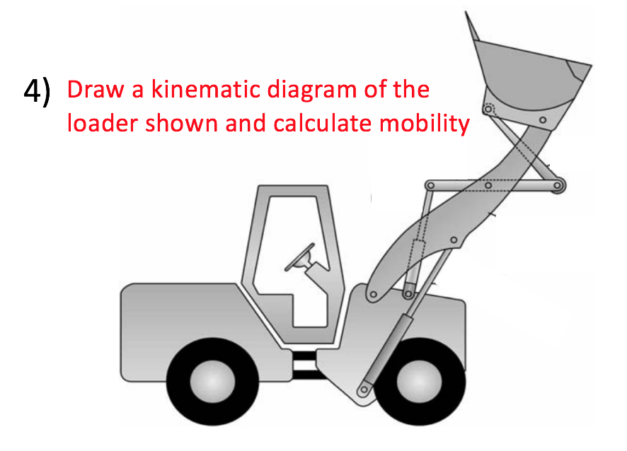
Solved 4 Draw A Kinematic Diagram Of The Loader Shown And Chegg Com

Front End Loader Bomford Turner

Compact Track Loader Part Diagram Construction Equipment Heavy Construction Equipment Heavy Equipment
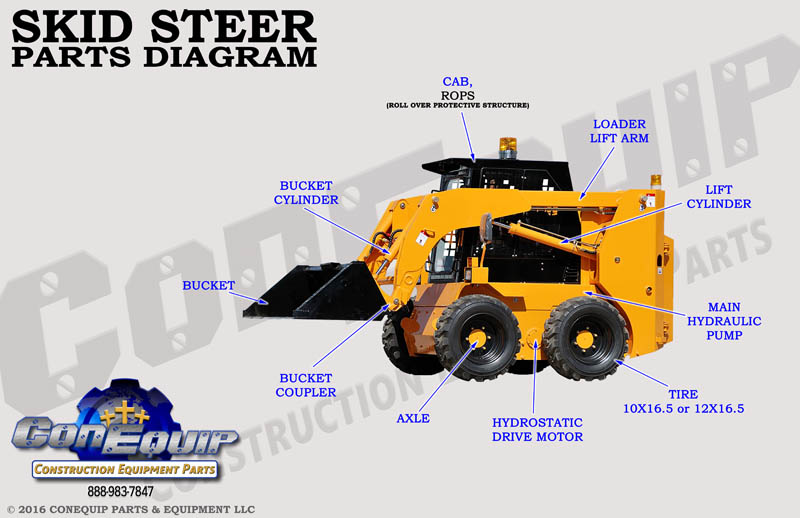
Skid Steer Part Diagram

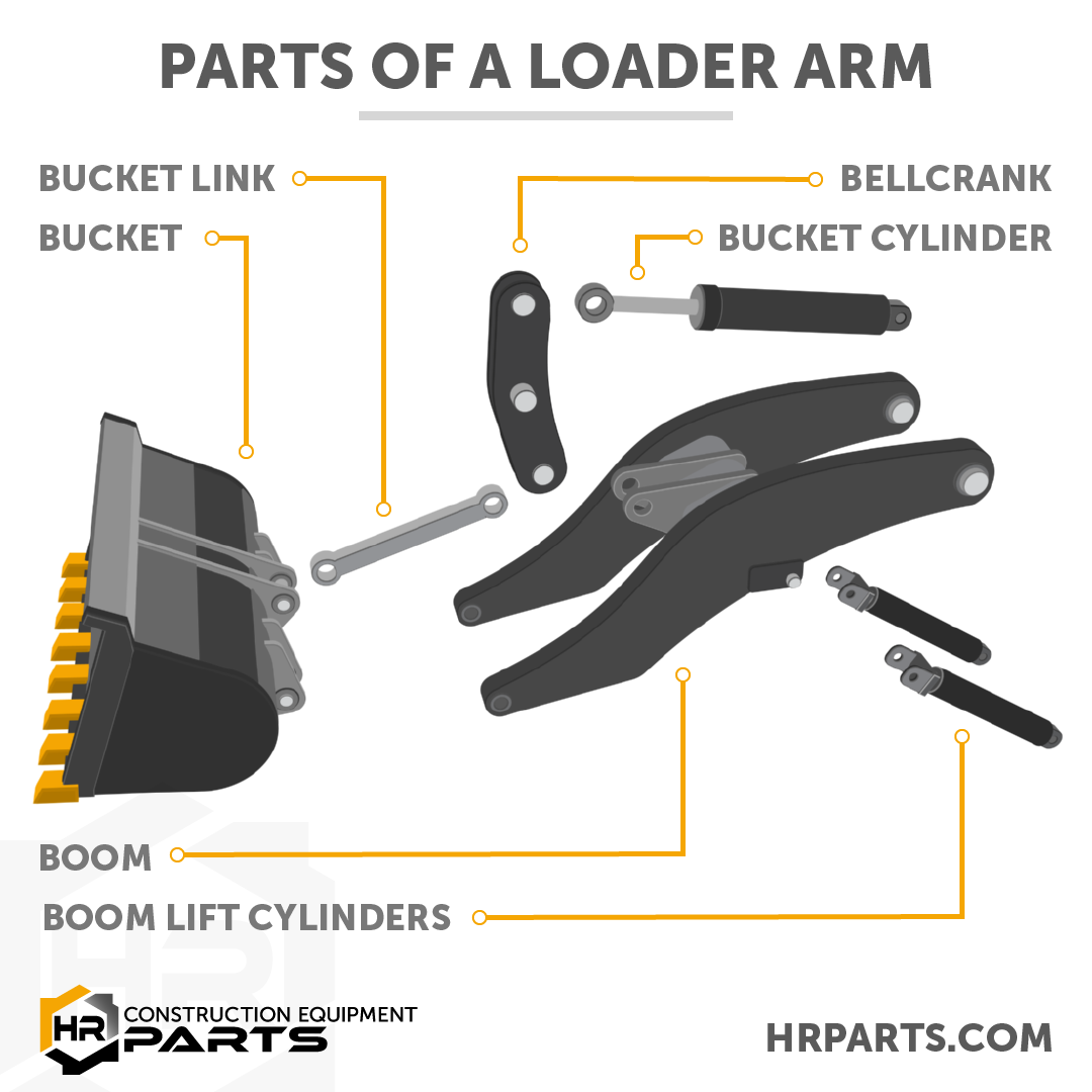
Lift Arm Of Skid Steer Loader Diagram Schematic And Image 02

Caterpillar 950f Shematics Electrical Wiring Diagram Download

Simplicity 990515 Front End Loader Parts Diagram For Hydraulics

General Loader Scheme Techblogmu

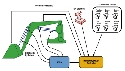
Modeling Of A Front End Loader For Control Design Semantic Scholar

Outline Drawing Of Wheel Loader Royalty Free Vector Image

Simplicity 1692932 Loader Front End Parts Diagram For Loader Front End Main Frame
Front End Loaders H360 Loader John Deere Ca
How A Wheel Loader Works Animation Diagram And Pictures
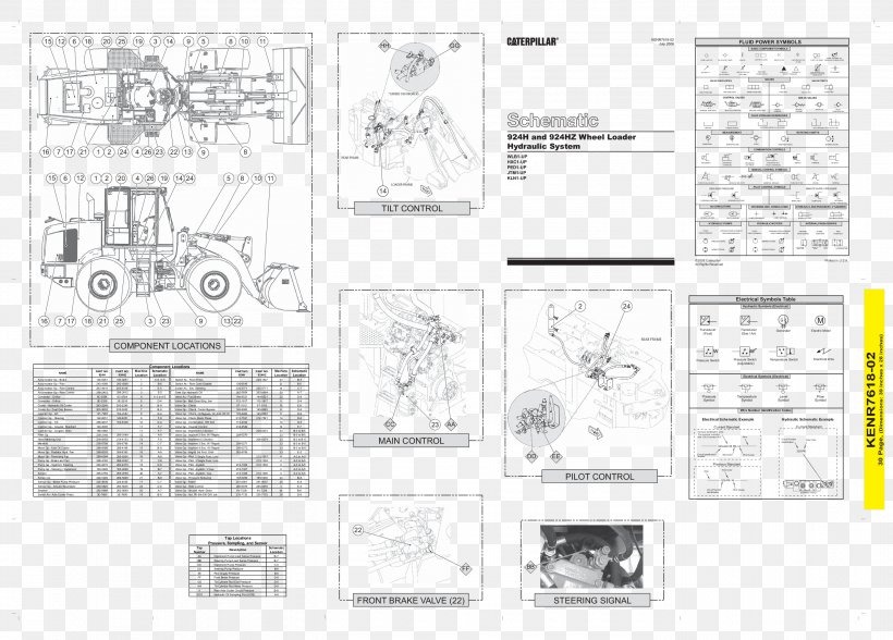
Caterpillar Inc John Deere Wiring Diagram Hydraulics Schematic Png 2808x2016px Caterpillar Inc Area Artwork Backhoe Loader

Research On Dynamic Behaviors Of Wheel Loaders With Different Layout Of Hydropneumatic Suspension Extrica Publisher Of International Research Journals

Loader Equipment Wikipedia

Cat 936 Wheel Loader Electrical System Schematic Manual Pdf Download By Heydownloads Issuu